

LG100 STANDARD – OPERATION AND TEST
LG100 – 120v/220/3 phase Operation & Use with a Dimmer
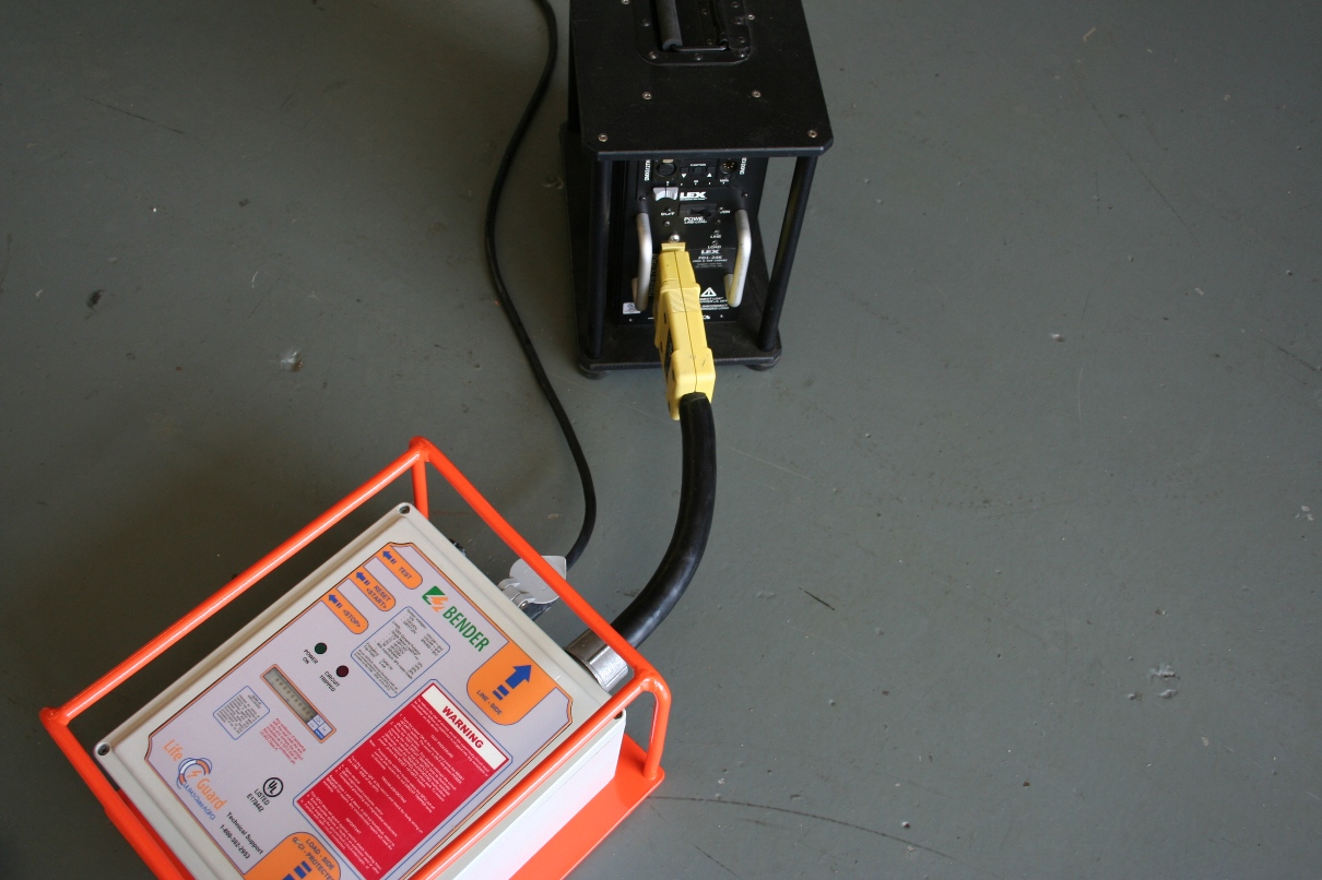
1– Confirm that the power is not energized.
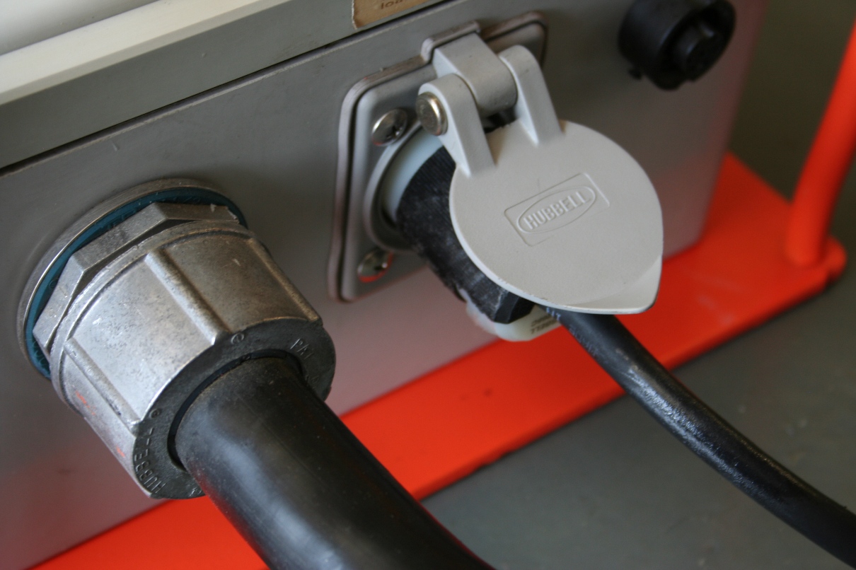
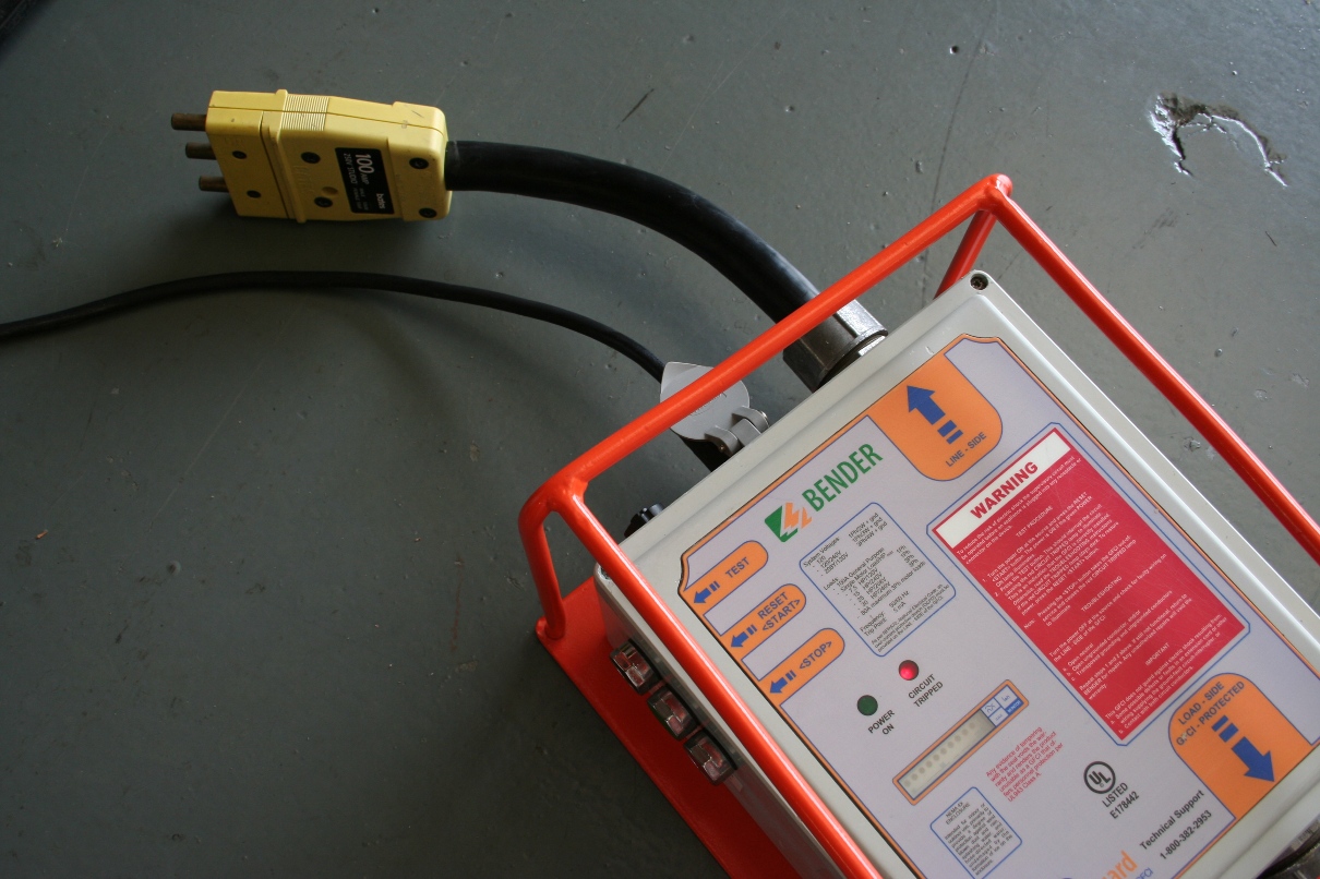
2- Connect the line side power. If GFCI unit has individual connectors then starting with the ground (green) connect camlock cable in this order to the line side: Green, White, Red, Blue and Black.
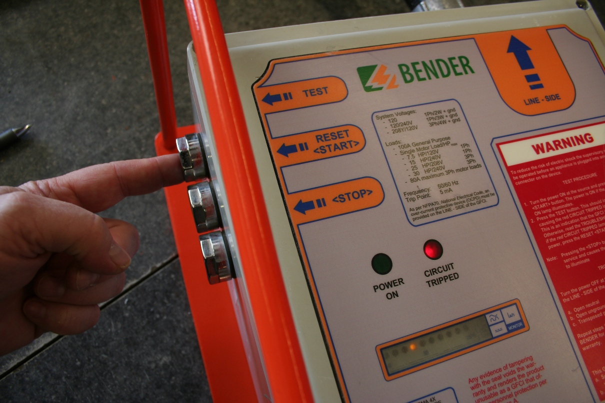
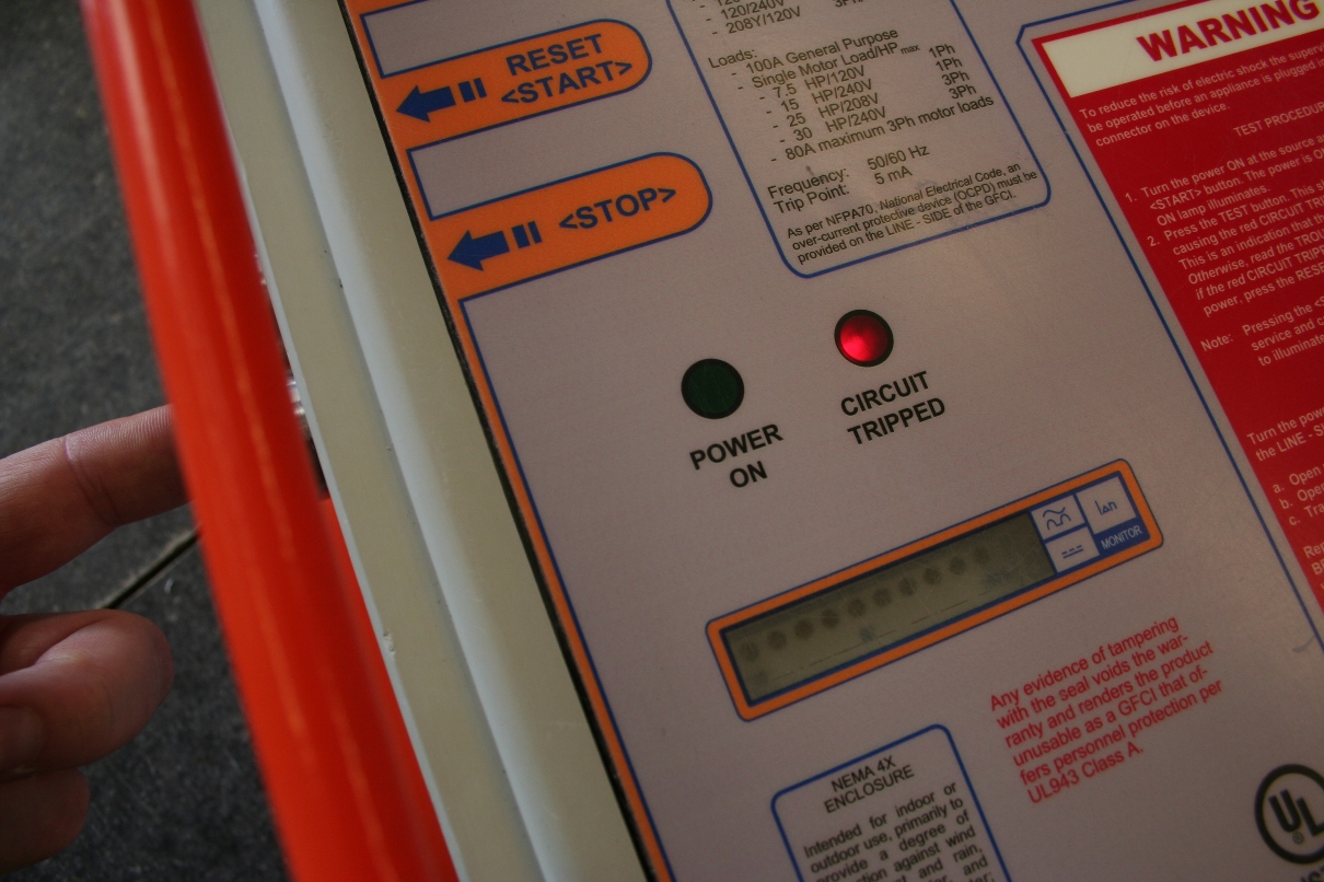
3- Before connecting anything to the load side, energize power. The red CIRCUIT TRIPPED indicator should be on.
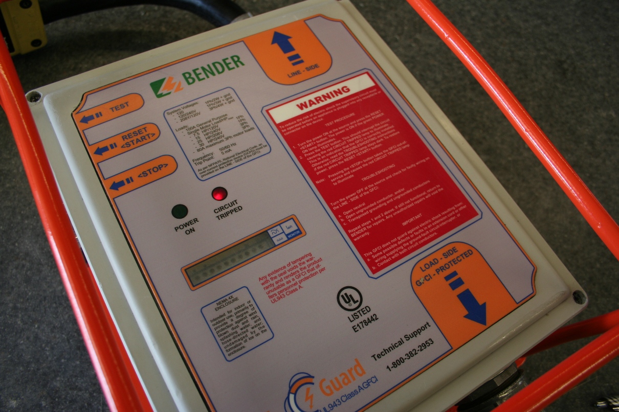
4- Turn on GFCI by pressing the RESET/START button on side of unit. Power on green indicator should be illuminated.
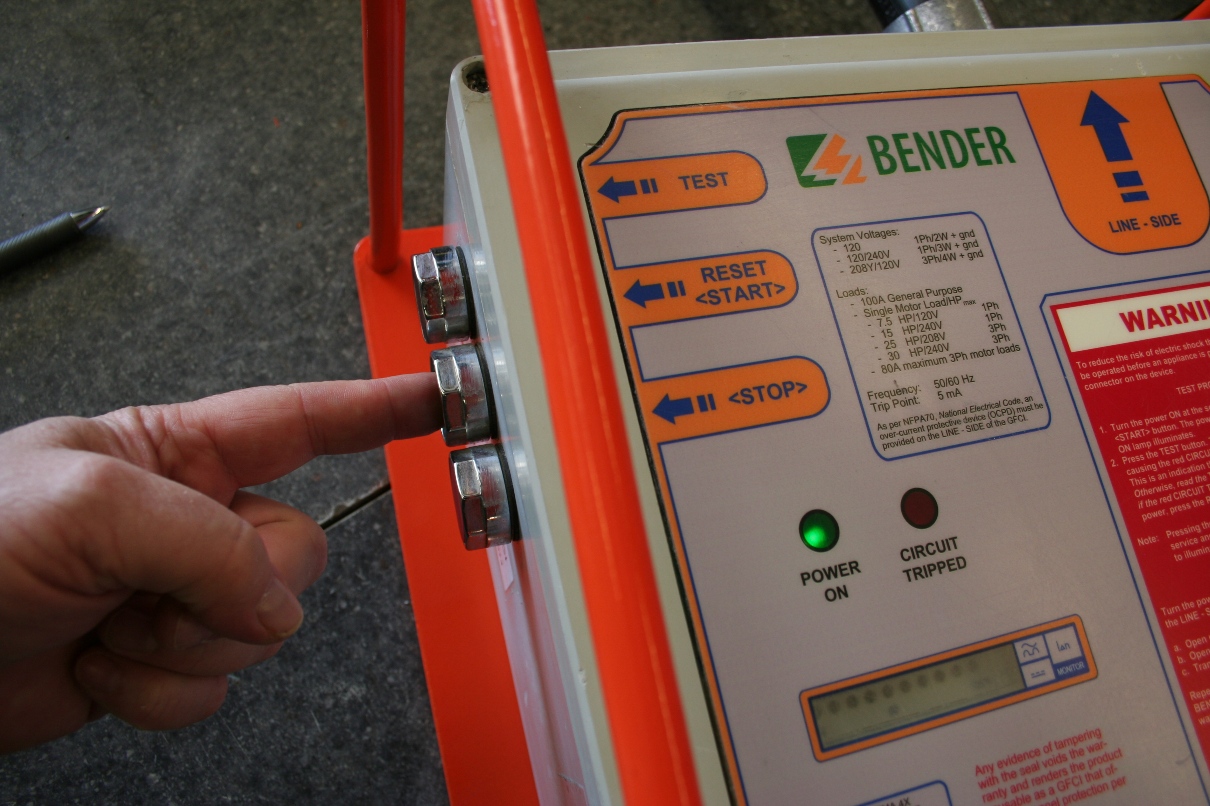
5- To test unit (It is recommended to test unit before each use) press and hold TEST button on the side of GFCI. If circuit is interrupted and the red CIRCUIT TRIPPED indicator is illuminated then the unit is working properly.
6- Once a test has been done and the unit is working properly. Press the STOP button and de energize the load side. Now the connections to the load side can be made. Remember, If GFCI has individual connectors then always make sure the Green then White are the first to connect. The reverse is true when disconnecting. Make sure the White then Green are the last to disconnect.
Using the LG100 with a Dimmer
NOTE: The LG100 should not be used with a dimmer on the LINE SIDE unless there is an auxiliary power feed connected as shown in STEP #1&2 – By using an auxiliary power source to control the GFCI the user can guarantee that the function of the device is not compromised by power that may be altered by the Dimmer.
1– Before unit is connected to any power, Connect the auxiliary power to a standard 120v Edison. (This should be connected to a GFCI as well if unit is close to a wet location)
2- When the 120v auxiliary power is energized the GFCI should show the CIRCUIT TRIPPED indicator on.
3- Preform a test on the unit by following steps 3 and 4 of the Operational/Test guide – This test assures the user that the GFCI is working properly and is not using a compromised supply voltage that may come from the Dimmer that is connected on the line side of GFCI.

4- Once a test has been done and the unit is working properly. Press the STOP button. Now, you can connect the the line side remember if GFCI has individual connectors then starting with the ground (green) then White, then Hot. Now you can connect the load side by following the same procedure.
5- Once the connections are made and the auxiliary power is connected press the RESET/START button to energize protected system. The dimmer should function normally.
